Some common questions about Quartz Crystal
1. No signal output from the crystal on oscillation circuit?
If there is no signal output measured by two terminals of the crystal using oscilloscope or frequency counter, please follow the instructions to determine the factors and possible solutions.
Step 1-1. Please examine the voltage of the in-terminal (Xin) and out- terminal (Xout) of the crystal and check whether the voltage is met according to IC spec.
Step 1-2. Please uninstall the crystal and test its frequency and load capacitance to see whether they vibrate and meet your specifications using a professional testing machine. You can also send it to your supplier to have them test it for you.
Step 1-3. If the crystal doesn’t vibrate, its load capacitance doesn’t match your specification, or there is a huge gap between current frequency and your targeted frequency, please send the crystal to your supplier to conduct Quality Analysis.
Step 1-4. If the frequency and load capacitance meet your specifications, but the problem also exists. The oscillation circuit evaluation will need to be executed. You can also send it to your supplier to have them test it for you.
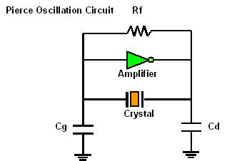
Step 1-5. The following figure is shown as the general oscillation circuit where Cd and Cg are external load capacitances, Rf is the feedback resistance, and Rd is the Limit Resistor.
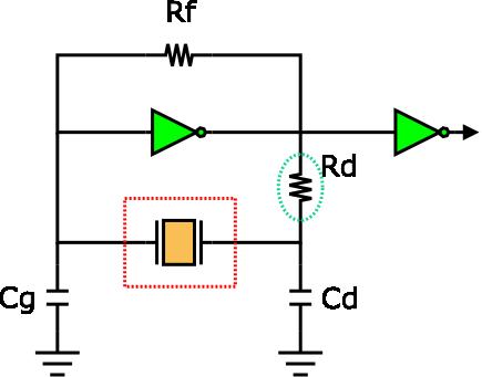
Negative resistance (-R) is the criterion to evaluate the quality of an oscillation circuit and its value should be at least five times of the crystal resistance in order to maintain a stable oscillation. Thus, it’s very important to measure the negative resistance following the instructions as below:
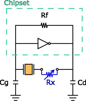
(1) Connect the resistance (Rx) with the crystal in series
(2) Adjust the value of Rx from the start point to the stop point of the oscillation.
(3) Measure the value of Rx during oscillating.
(4) You will be able to obtain the value of negative resistance, |-R| = Rx + Re, and Re = effective crystal resistance.
Step 1-6. If the negative resistance of IC is too low to drive the circuit, we propose three solutions to improve such case.
(1) Lower the value of limit resistor (Rd). However, you should also confirm if the frequency shift and crystal driving current meet specifications at the same time.
(2) Lower the value of external capacitance (Cg and Cd), and adopt other crystal with lower load capacitance (CL).
(3) Adopt a crystal with lower resistance (Rr).
2. System is not functioning due to the deviation of frequency output is over the limit?
Step 2-1. If the frequency measured by frequency counter is over the limit, we should increase the external capacitance, CL ( or the values of Cd & Cg ), to lower the frequency to our targeted frequency, vice versa.
Step 2-2. We could adopt a crystal with lower capacitance if the frequency is much higher than the targeted frequency, vice versa.
3. What is the test method for crystal parameter?
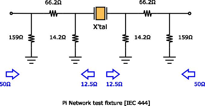
Connect a “pi Circuit” to a Network analyzer with the function to measure equivalent constant and measure it. JIS and IEC specify the shape and the internal resistance of the “pi Circuit” fully shown as below.
4. How to depict the operation principle of the oscillator circuit?
Crystal controlled oscillators may be considered as consisting of an amplifier and a feedback network that selects a part of the amplifier output and returns it to the amplifier input. A generalized depiction of such a circuit is shown below.
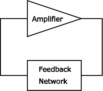
In order for an oscillator circuit to operate, two conditions must be met: (A) The loop power gain must be equal to unity. (B) The loop phase shift must be equal to 0,2π,4π, etc. radians
5. What is series or parallel resonant frequency?
As is apparent from below figure, quartz crystal unit has two frequencies of zero phase. The first, or lower of the two, is the series resonant frequency, usually abbreviated as Fs. The second, or higher of the two frequencies of zero phase is the parallel, or anti-resonant frequency, usually abbreviated as Fa. Both the series and parallel resonant frequencies appear resistive in an oscillator circuit. At the series resonant point, the resistance is minimal and the current flow is maximal.
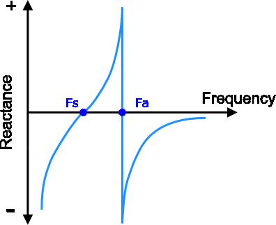
At the parallel point, the resistance is maximal and the current flow is minimal. Therefore, the parallel resonant frequency, Fa, should never be used as the controlling frequency of an oscillator circuit.
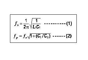
A quartz crystal unit can be made to oscillate at any point along the line between the series and parallel resonant points by the inclusion of reactive components (usually capacitors) in the feedback loop of the oscillator circuit. The fs and fa frequencies are determined by the piezoelectric ceramic material and its physical parameters. The equivalent circuit constants can be determined from the following formulas:
6. What is CL value of crystal? What is its influence on?
All quartz crystal resonators have a series resonant frequency (fs, frequency of lowest impedance). At this frequency, the crystal appears resistive in the circuit. Crystals can be “pulled” from this series frequency by adding reactance (capacitance) in series with the crystal. When operated in combination with an external load capacitance (CL) the crystal oscillates in a frequency range slightly above its series resonant frequency. This is the parallel (load resonant) frequency.
When ordering a parallel crystal, always specify the nominal parallel resonant frequency and the amount of load capacitance in Pico Farads (pF). For example, a standard value of CL (such as 15pF) can be ordered; the capacitor values are then calculated to match the crystal CL.
The load frequency is dependent on the CL value, and its formula is showed below.

If the output crystal frequency is higher than targeted frequency, you should increase the external capacitance, CL (or the values of Cd & Cg), to lower the frequency to your targeted frequency. Another method is that adopt a crystal with lower capacitance if the frequency is higher than the center frequency.
7. The frequency pullability of the crystal is not enough or the pulling range is asymmetric.
(1) As shown below, there is inverse correlation between the load capacitance of circuit and pullability. It shows that the frequency pulling range will be larger when the load capacitance gets smaller, vice versa.
(2) On the other hand, the crystal characteristics also affects the frequency pulling range. For instance, there are Trim Sensitivity (TS), Co, and C1. The fractional frequency change for an increment change of the load capacitance is called TS. The frequency pullability gets larger when C1 gets larger or Co gets smaller.
(3) If the pulling range is asymmetric, i.e. the pulling of one side isn’t enough and the other is too large, we can adjust the load capacitance value of crystal.
8. The load crystal frequency on pcba has spread distribution.
Owing to the relationship between the frequency pullability and the load capacitance, the smaller the load capacitance is, the more sensitively the frequency change. The following steps are shown below.
(1) Increase the load capacitance, Cg and Cd, and use the crystal with larger CL.
(2) Using more precise capacitors, Cg and Cd.
(3) Using more precise crystal.
9. The common problem of products.
1). General cleaning solutions or ultrasonic cleaning method may be used to clean our products. However, under certain circumstances, ultrasonic cleaning machine could generate resonance at the oscillation frequency of our products and thus deteriorate the electrical characteristics in devices, and even damage the overall structure of devices. Therefore, verification test is recommended before cleaning.
2). Tuning fork products oscillate at frequency bands that are close to the washing frequency of ultrasonic cleaning machine, which may cause resonance deteriorating the electrical characteristics in devices, and even damaging the overall structure of devices. Therefore, using ultrasonic cleaning machine to clean tuning fork devices should be avoided. If the use of this method to clean tuning fork devices is required, it’s suggested to check the functionality of devices before and after the cleaning process.
3). Please avoid any circuit under the product when laying out for preventing interference.
4). Please do not connect to any circuit when the datasheet marked as “NC” or “Do not connect” to avoid error function.
5). Avoid mounting and processing by Ultrasonic welding, this method has a possibility of an excessive vibration spreading inside the crystal products and becoming the cause of characteristic deterioration and not oscillating.
6). Hand soldering Temperature: The soldering temperature should be between 350°C and 370°C .
Hand soldering Time: The heating time for manual soldering should typically be completed within 3-5 seconds
10. What the parameters are necessary when the customers buy the crystals?
Main information:
Nominal Frequency、Capacitance of Load、Tolerance( ±ppm)
Secondary information:(depends on Genuway Technology or industry standard)
Dimension, ESR(Equivalent Series Resistance), C0(Shunt Capacitance), Operating temperature range.
11. How to affect temperature characteristic by the cut angle of the crystal quartz?
Since discovered the piezoelectric effect in quartz crystals, which appearance of an electric potential across certain faces of a crystal when it is subjected to mechanical pressure.
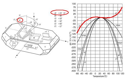
According to different cut angles to quartz bars, there are different kinds of quartz plates, for examples, AT, BT, CT-cut plates different types of quartz cuts, have different available elastic, piezoelectric and different properties, which are the basic parameters for designing a quartz crystal device. The most often used Quartz- cut types are AT-cut angle +35° 15’ shown as below figures schematically.
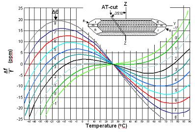
Especially, the frequency-temperature characteristic of AT-cut angle is more stable than other cut angles.
12. What are features with the AT-cut of the crystal quartz?
AT-cut is the most popular cut angle in the quartz crystal device. The temperature coefficient is only dominated by a third–order function of temperature deviation. Also, it has excellent frequency stability over a wide temperature range. The specification of the crystal frequency-temperature characteristic was decided by the fine tune of the cut angle and operating temperature range. The figure showed as below:
13. What is the effect to output frequency when crystal CL and PCBA CL are mismatch?
We produce the crystal CL to satisfy the customer’s request. Nominal frequency means that the crystal CL and the PCBA CL meet (no frequency deviation) each other in the oscillator circuit in order to satisfy with the customers.
If the CL of PCBA is higher than the crystal, the output frequency should lower than the nominal frequency.
If the CL of PCBA is lower than the crystal, the output frequency should higher than the nominal frequency.
14. How to calculate the CL?
Use this formula to approximate the value of capacitors needed:
CL=((C1 x C2) / (C1 + C2)) + Cstray
Cg & Cd are external capacitances in the Pierce Oscillation Circuit
Cs is the stray capacitance in the circuit, typically 3-5pF.
